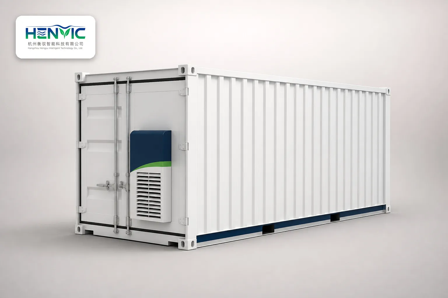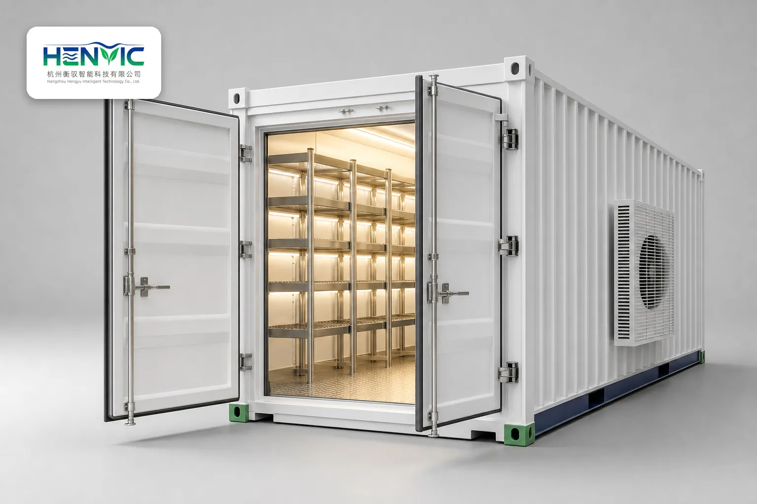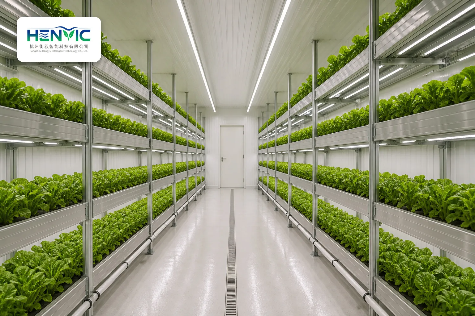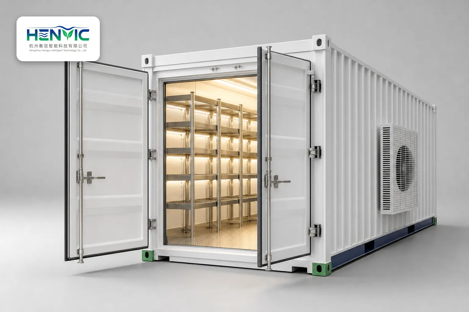
A cultivation container — the "grow box," "farm container," or "nursery container" that dominates the conversation around controlled-environment agriculture at small scale — is best understood not as a greenhouse made of steel but as a sealed, heavily instrumented thermal enclosure in which every cubic decimetre and every watt is contested. Its internal organisation is dictated by one brutal geometric fact: a corrugated steel ISO shell has a fixed, narrow, low envelope (2.35 m internal width, 2.39 m or 2.69 m internal height), so the layout problem is not "how much space do we have" but "how much space survives insulation, racking, ductwork, and the human body." Everything else — the growing system, the lighting, the climate loop, the plumbing, the control layer — is arranged to fit inside that constraint without creating a condensation, airflow, or biosecurity failure.
The following is a full anatomy of that interior, organised the way an engineer would actually build it: envelope first, then zoning, then the five functional chains that occupy the volume.
1. The Envelope: What You Start With
Before any interior work, the base structure sets the hard limits.
Parameter
20 ft standard
40 ft standard
40 ft high-cube
External (L×W×H)
6.058 × 2.438 × 2.591 m
12.192 × 2.438 × 2.591 m
12.192 × 2.438 × 2.896 m
Typical internal (L×W×H)
≈5.898 × 2.350 × 2.393 m
≈12.032 × 2.350 × 2.393 m
≈12.032 × 2.350 × 2.695 m
Floor area (internal)
≈13.7 m² (147 ft²)
≈28.3 m² (305 ft²)
≈28.3 m² (305 ft²)
Tare mass
≈2.2–2.4 t
≈3.7–4.0 t
≈3.9–4.2 t
Max gross rating
24,000–30,480 kg depending on CSC plate
30,480–32,500 kg
30,480–32,500 kg
Three structural consequences follow immediately.
The high-cube is almost always the correct choice. The extra 305 mm of internal height is what makes multi-tier racking with a walkable service aisle, or a top-lit canopy with adequate lamp-to-crop distance, physically possible. In a standard-height box, a 1.9 m operator plus a 1.75 m rack plus a lighting tier simply does not stack.
The corrugated wall is a thermal and hygienic liability. Corten steel has essentially no insulating value, and the corrugation profile creates hundreds of metres of ridges and troughs that are impossible to clean, trap condensation, and shelter mould. The interior is therefore never left bare: it is lined. The usual approach is closed-cell spray polyurethane foam applied to walls and roof (typically 50–100 mm, giving roughly R-20 to R-35 depending on density and thickness), followed by a sealed, washable facing — food-grade PVC, stainless panels, or a painted/epoxy-coated membrane. This lining consumes 100–250 mm of the envelope on every side, which is the single largest volume loss in the whole build and the reason "internal growing area" figures in vendor brochures are so frequently inflated.
Thermal bridging is unavoidable and must be designed around. The corner posts, top and bottom rails, and door frames are continuous steel paths from outside to inside. In a cooled, humid interior operating in hot ambient conditions, these surfaces fall below the interior dew point and sweat. The standard mitigation is a thermal break: an intermediate framing layer (timber or, preferably, galvanised steel standoffs with a compressible gasket) to which the interior liner is attached, so that no rigid metal member spans from the outer skin to the inner surface. Skipping this is the most common cause of the mould-behind-the-panel failure that appears 12–18 months after commissioning.
The floor is a separate problem. The original marine plywood is a 28 mm bamboo or plywood deck designed for forklift point loads, not for standing water. In a hydroponic container it must be sealed (epoxy or membrane), sloped to a drain, and — critically — protected from the salt and nutrient solution that will otherwise wick into the ply and cause delamination. Most serious builds install a raised false floor or a fully welded stainless tray over the deck.
2. Zoning: How the Volume Is Divided
A competent container interior is not one room. It is a sequence of pressure- and hygiene-separated zones arranged along the long axis.
Zone 0 — Exterior apron / equipment end. One short end (typically 1.0–1.5 m of length) is bulkheaded off as a technical compartment, either inside the box or as an external canopy/box mounted to the door end. It houses the electrical panel, nutrient dosing units, reservoirs, chillers or heat pumps, dehumidifier, and reverse-connection plumbing. Putting this inside the container costs growing area; putting it outside exposes it to weather and theft. The usual compromise for a 40 ft HC is a 1.2 m internal mechanical bulkhead, because it keeps the dosing pumps within a short run of the crop, protects equipment from UV and rain, and lets the whole unit be moved as one box.
Zone 1 — Vestibule / airlock. The door end, or a partitioned section of 0.6–0.9 m, functions as a change and buffer zone. Its purpose is twofold: it prevents the full opening of the insulated door onto the crop (which would dump the entire interior air volume and its thermal content in one exchange), and it provides a place for shoe change, hand sanitising, and gear. In a production unit growing leafy greens for raw consumption, this is the cheapest available pest and pathogen barrier. It is also where the positive-pressure strategy is implemented — the growing zone is held at slight positive pressure relative to the vestibule so that leakage flows outward through any gap rather than drawing in unfiltered, spore-laden air.
Zone 2 — Growing zone. The remaining length (roughly 9.5–10.5 m in a 40 ft HC after mechanical and vestibule deductions) is the crop volume. It is organised as two long runs of racking separated by a central aisle, or as a single wall-mounted run plus a mobile rack. This is discussed in detail in the next section.
Zone 3 — Propagation / nursery sub-zone. Where the container is used as a nursery rather than a finish-farm — seedling production, cuttings, tissue-culture acclimatisation, cover-crop starts — the interior is split into two independent climate sections along the length, separated by an insulated partition with its own door. The justification is that propagation and finishing have incompatible setpoints: propagation wants 22–26 °C air, 70–85 % RH, and low PPFD (100–200 μmol·m⁻²·s⁻¹); finishing wants lower humidity (50–65 % RH), higher PPFD, and stronger transpiration-driven airflow. Sharing one climate between them means running one of the two badly and paying for the excess energy. The partition also isolates a damping-off or thrips outbreak to one half.
3. The Growing Structure: Racking, Aisles, and the 2.35 m Problem
The internal width of 2.35 m is the governing constraint on rack geometry, and it produces one of two canonical layouts.
Layout A — Twin fixed racks with a central aisle. Two racks of 600–700 mm depth run along each long wall, leaving a 900–1100 mm central aisle. This is the layout of choice for leafy greens and herbs because it gives the operator access to both faces of every tier and permits rolling a harvest trolley through. The rack depth is not arbitrary: a shelf deeper than about 750 mm becomes unreachable at the rear for a person standing in the aisle, and the structural moment at the bracket doubles with depth. Tier count is set by the internal height. In a 40 ft HC with 2.695 m internal height and a 100 mm liner, the usable height is roughly 2.55 m; allowing 400–500 mm of vertical pitch per tier (which must accommodate plant height, lamp thickness, and the gutter/tray), you get four to five tiers, with the topmost tier's lamp typically at 2.2–2.3 m — the practical limit for a 1.75 m operator to reach with a step stool. Total growing surface in such a unit lands in the region of 45–60 m² (about 500–650 ft²) of canopy.
Layout B — Single wall rack plus mobile/rotating racks. A 1000–1200 mm deep rack on one long wall, with a narrower aisle and a rotating or sliding rack on the opposite side. This increases canopy per square metre of floor at the cost of service complexity and structural risk (a rotating rack loaded with 40 kg of wet substrate is a serious injury mechanism if a bearing fails).
Layout C — Floor-level NFT or DWC beds (no vertical stacking). Used for vine crops (tomato, cucumber, pepper), strawberries on elevated gutters, and nursery trays on benches. Here the container is treated as a walk-in tunnel rather than a stack, and the vertical volume above the canopy is used for airflow distribution and CO₂ delivery rather than for more plants.
The aisle width deserves a specific note because it is the most commonly regretted decision. Under 750 mm, an operator cannot turn while carrying a tray; under 600 mm, a collapsed or leaking rack becomes unrepairable in place. Anything above 1100 mm in a container this narrow is wasted growing area. The practical answer is 900 mm clear, measured between the outer faces of the trays, not between the rack frames — a distinction that quietly eats 100–150 mm in most builds.
4. The Root-Zone Chain: Hydroponic Subsystem Organisation
Inside the racks, the root-zone delivery system is arranged as a closed loop with five physical components, each of which occupies volume and each of which is a contamination point.
Reservoir. Typically 100–400 L of food-grade HDPE or stainless, located in the mechanical zone or as an under-bench tank. Under-bench placement recovers floor area but creates a serious maintenance problem: a tank you cannot see or reach without removing plants is a tank you will not clean. Reservoir volume is sized against dosing control stability — a common rule of thumb is that the reservoir should hold at least one full circuit of the system's pipe and channel volume, and preferably enough that a dosing error takes minutes rather than seconds to reach the roots.
Pumps and circulation. A primary transfer pump (often 40–80 W in a container-scale unit) plus, in recirculating systems, a circulation loop sized to achieve a target turnover. Redundancy is a design decision with a hard deadline: in NFT (nutrient film technique) channels, a root mat exposed to air without nutrient flow begins to desiccate within roughly 1–2 hours in a warm container. Serious builds therefore include either a second pump on an automatic changeover, or a system architecture that can hold a bank of plants for hours without flow (DWC and drip-on-coco tolerate outage far better than NFT).
Distribution channels. The three families and their container-specific trade-offs:
• NFT — shallow sloped channels, thin flowing film. Highest water- and nutrient-use efficiency, fastest response to dosing changes, best oxygenation per litre. Requires precise slope (typically 1:30 to 1:100) and is intolerant of level error across a rack; in a container whose frame can twist slightly during transport, re-levelling after every relocation is mandatory. Pump-failure vulnerability is the highest of the three.
• DWC / raft — roots suspended in aerated solution. Excellent thermal buffering because of the large water mass, very forgiving of pump interruption (air stones fail before pumps do), high yields of leafy greens. Costs: water volume and mass. A DWC system in a container can add 1–2 tonnes of water load, which must be checked against the floor's point-load capacity and the site foundation. Also the highest risk of pathogen amplification (Pythium, Ralstonia) because a single infected plant can seed a whole shared tank.
• Aeroponics / mist — roots in air, nutrient delivered as fine spray. Highest oxygen, lowest water use, best growth rates per unit of solution. Demands fine nozzles (typically 50–100 μm droplets) that clog with any precipitation or biofilm, and a filtration stage most container builds omit. The failure mode is nozzle blockage, which presents as a patch of stunted plants long before anyone thinks to check the manifold.
Drainage and return. Every channel needs a fall to a return point, and every return needs a screen. The screens — 200–400 μm — are the single most neglected component in container farms; a clogged return causes overflow into the aisle within minutes.
Sterilisation stage. Inline UV (typically 30–80 W low-pressure or medium-pressure lamps sized to flow rate and required dose) or ozone, on the return line before the reservoir. Ozone is effective against waterborne pathogens and biofilm but requires off-gas management and careful ORP control (commonly held in the 0.3–0.5 mg/L residual range for container systems, with tight control because the margin to phytotoxicity is narrow). Its use should be validated against the specific crop, since some root-zone microbiology is deliberately introduced in biological-control programmes and ozone will destroy it.
Sensor set at the root zone. EC, pH, water temperature, and level, all logged. Water temperature is the variable most often left unmonitored and most often responsible for crop loss: above roughly 22–24 °C, dissolved oxygen falls and Pythium sporulation accelerates sharply. In a container with a dark reservoir absorbing stray light and heat from the lamps, this is a real and recurring problem, which is why a small water chiller is not a luxury item but a component of the root-zone chain.
5. The Light Chain: Photometry Before Fixture Selection
Lighting is the largest single energy consumer in a container farm — commonly 50–70 % of total connected load — and it is also the largest heat source, which makes it simultaneously the lighting system and the cooling load.
The design sequence must start with the target, not the product. For leafy greens and herbs, the working targets are usually a canopy-level PPFD of 150–300 μmol·m⁻²·s⁻¹ and a daily light integral (DLI) of 12–17 mol·m⁻²·d⁻¹ over a 16–18 hour photoperiod; fruiting crops push PPFD to 400–700 and DLI to 20–30, which is where a container's electrical service and heat rejection usually become the binding constraint rather than the lamps.
From the target, the required installed flux follows:
Installed μmol/s ≈ (canopy area in m² × target PPFD) ÷ (uniformity factor × fixture utilisation at the working distance)
The uniformity and utilisation factors are where brochure numbers stop matching reality. A fixture rated at a certain photon flux will deliver measurably less at the canopy once you account for the distance from lamp to leaves, the shadowing of adjacent tiers, and the reflectance of the rack structure. In a narrow container, the walls can be used as reflectors — a white or mirrored liner raises effective PPFD at the outer edges of the canopy by a meaningful amount, but it also creates hot spots and complicates the airflow pattern.
Fixture architecture in a container is constrained by tier pitch. With 400–500 mm between tiers, there is no room for suspended high-bay panels. The workable forms are thin horizontal bars or boards mounted directly under each shelf (top-lighting the tier below), and vertical side-bars for tall or dense canopies. Bar-style fixtures give better canopy uniformity across a narrow rack than a single central panel, because the light arrives from multiple directions rather than one plane.
Efficacy is the number that determines operating cost. Commercially available horticultural LED fixtures in current production typically sit in the region of 2.5–3.2 μmol/J at the fixture level, with the upper end of vendor claims reaching 3.5 or slightly above; these figures come from supplier datasheets and are not measured under identical conditions, so they should be treated as a range rather than a ranking. The practical arithmetic: a container with 50 m² canopy at 200 μmol·m⁻²·s⁻¹ needs on the order of 10 kW of installed photon output; at 2.8 μmol/J that is roughly 3.6 kW of electrical input, and at 2.2 μmol/J about 4.5 kW — a difference of nearly a kilowatt running 16 hours a day.
Spectrum is a crop-quality lever, not a growth-rate lever. A broad "white" spectrum with a warm-to-neutral correlated colour temperature plus supplemental deep-red (around 660 nm) covers most leafy production and lets the operator actually see the plants — which matters for scouting. Far-red (around 730 nm) drives shade-avoidance and stem elongation, useful in propagation and fruiting but actively harmful if you want compact, dense lettuce. Blue fraction governs stomatal conductance, anthocyanin development, and leaf thickness; reducing blue in the final weeks is a known technique for increasing leaf area and tenderness at the cost of structural firmness. UV-A at low doses is used deliberately in some specialty crops to raise flavonoid content. GB/T 44473-2024, the Chinese performance specification for plant-lighting LEDs and modules, formalises band-by-band conformity testing for exactly this reason — spectral claims need to be measured, not asserted.
Controls. Dimming must be smooth and flicker-free (flicker at line frequency interferes with high-speed camera inspection and can confound some plant-measurement systems), and the schedule should support sunrise/sunset ramps, which reduce tipburn incidence in some cultivars by moderating the abrupt onset of transpiration.
6. The Climate Chain: Air, Water, and the Heat Budget
A container's surface-to-volume ratio is roughly three times that of a warehouse of equivalent crop area. That is simultaneously an advantage — insulation is cheap per cubic metre — and the core difficulty: every watt of lamp heat, every gram of transpired water, has to be rejected through a very small wall area.
The heat load has two components. Radiant and convective heat from the lamps (essentially all electrical input to the lighting becomes heat inside the box), and latent heat from transpiration, which is removed by condensation in the cooling coil rather than by sensible airflow. The latent fraction in a densely planted, high-PPFD container is large — often 40–60 % of total cooling load. A cooling system sized only on the sensible number will run continuously at part load, never dehumidify properly, and produce a wet, sticky interior within weeks.
The equipment options and their fit. Ducted split heat pumps are the most common and cheapest, but standard comfort AC units are poorly suited: they are designed for sensible loads and short run cycles, and in a container they often fail to reach dew point on the coil consistently. Purpose-built vertical-farming air handlers combine a larger coil, higher static pressure for ducting and filters, and an integrated refrigerant dehumidification circuit. Dedicated desiccant or refrigerant dehumidifiers are added when RH control cannot be achieved by temperature alone — which is the normal situation in winter, when the cooling load collapses but transpiration continues.
Air distribution is a solved geometry problem if you do it deliberately. The standard pattern is a supply plenum running the full length along the ceiling (or a ducted series of outlets per tier) with a return at the opposite end near the floor, creating a cross-flow that sweeps each canopy. Per-tier oscillating fans are then added not to move bulk air but to raise boundary-layer conductance at the leaf surface — the mechanism by which airflow actually reduces tipburn and strengthens tissue. The mistake is pointing fans directly at the crop at high speed, which over-dries leaf margins and produces exactly the tipburn it was meant to prevent.
CO₂. Ambient air at roughly 400–450 ppm is the practical ceiling in a sealed container unless supplementation is added. With LED PPFD above about 300 μmol·m⁻²·s⁻¹, CO₂ becomes co-limiting with light, and enrichment to 800–1200 ppm can produce a substantial yield response — but only if ventilation rates, dosing control, and a leak-tight enclosure are all in place. In a container with a door gasket that has been compressed by transport, enrichment quietly leaks out and the capital spent on a CO₂ system buys nothing. This is why CO₂ enrichment is common in warehouse-scale vertical farms and rare in containers: the enclosure quality is usually not there.
Condensation management. Every cold surface inside the box — the coil housing, refrigerant lines, water supply pipes, the metal frame of a rack near a cold spot — is a potential drip onto a canopy. Drips are a disease vector (they spread Botrytis and bacterial leaf spot) and a food-safety concern. Insulation of all cold lines, a condensate collection and pump-out path, and keeping interior surfaces above dew point via dehumidification rather than overcooling are the three countermeasures.
7. The Electrical Chain
Service sizing. A 40 ft HC production unit with 50 m² of canopy typically presents a connected load in the region of 10–20 kW — lighting dominating, then HVAC, then pumps and controls — with startup inrush from compressors adding a transient. Many single-phase domestic services will not carry this reliably; three-phase supply (or a substantial single-phase upgrade) is the norm for production units. Off-grid configurations with solar plus battery storage exist and are technically coherent, but the battery mass and the winter-autonomy problem make them a cost decision rather than an engineering one.
Internal organisation. A main distribution panel in the mechanical zone, with separately protected circuits for lighting (often on dimmers/drivers with their own thermal limits), HVAC, pumps, dosing, and controls. Lighting circuits should be segregated from sensitive sensor and control wiring because LED drivers inject switching noise. Ground-fault and surge protection matter more than usual because the interior is a wet environment inside a conductive metal shell — this combination is why equipment grounding and RCD/GFCI protection on every circuit in the grow zone are non-negotiable, and why bonding the container shell itself to the earthing system is required rather than optional.
Heat from the electrical chain is not negligible. Driver losses, distribution losses, and the ballast-equivalent losses in older fixtures all add to the cooling load, which is one of the quieter arguments for placing drivers in the mechanical zone or outside the thermal envelope rather than inside the grow volume.
8. The Control and Instrumentation Chain
Sensor placement determines data quality more than controller capability. The minimum credible set: air temperature and RH at canopy level at both ends of the box (the gradient along a 10 m container is real and often 2–4 °C), VPD derived from those, CO₂, root-zone EC/pH/water temperature, and a light sensor at canopy level rather than at the fixture. A controller reading only one point in a container is reading the exhaust air, not the crop.
Actuation. Relay and 0–10 V / DALI control of lighting zones, compressor and fan stages, dehumidifier, dosing peristaltic pumps, and circulation pumps. Interlocks matter more than the dashboard: a pump-off alarm that also shuts the lights (because lamps at full output with no transpiration cooling in a dead system is a fast oven), a high-water-temperature alarm that triggers the chiller, and a hard limit on reservoir level to prevent a leaking fitting from flooding the electrical panel.
Fail-safe logic. The single most valuable feature in an unattended container is not remote monitoring — it is a locally executed safe state that does not depend on network connectivity. Remote dashboards that require the internet to trigger a pump restart are not a control system; they are an alarm system with a latency problem.
Data. Logging at 1–5 minute intervals, retained long enough to reconstruct a crop cycle. This is where container farms most often fail commercially: without a time series linking environmental excursions to yield and quality outcomes, the operator cannot tell whether a change in lighting recipe helped or whether the weather just happened to cooperate.
9. The Human and Biological Interface
Ergonomics. Working at height in a 2.35 m wide box means the operator is either reaching above shoulder height across a rack or crouching. Tier pitch, tray weight (a wet tray at 8–15 kg lifted 400 times a day is an injury mechanism), and the availability of a stable platform are the design parameters that determine whether the unit can be harvested by one person in a reasonable shift. The door itself — a 40 ft container's doors are heavy and, on a high-cube, awkward to hold open while moving a trolley — is a daily friction that most buyers underestimate.
Sanitation and material compatibility. Every surface in contact with plants or nutrient solution must be cleanable and non-absorbent. Corrugated steel, unpainted timber, and porous plastic all shelter biofilm. The clean-in-place routine for a container is realistically manual: a removable tray system that can be taken to a wash station beats an integrated system that cannot be disassembled.
Pest exclusion. Insect screens on any intake, sealed penetrations for pipes and cables (each conduit through the wall is a potential entry point for Thrips and Radicus mites), and a sticky-trap monitoring grid. The vestibule's positive-pressure strategy only works if the enclosure is tight, which brings the design back to door gaskets and penetration sealing — details that are cheap at build time and expensive retrofitted.
10. Nursery-Specific Internal Arrangement
Where the container's function is propagation rather than production, the interior organisation shifts in four ways.
Benches instead of tall racks. Trays sit at bench height (750–900 mm) on a single or double tier, because the work — seeding, pricking out, hardening — is done standing at a comfortable height, and the plants are short. This sacrifices canopy area per floor area but gains throughput of hands-on labour, which is the binding cost in a nursery.
Humidity domes and misting. Rooting cuttings and germinating seed need RH above 85–95 %, which is incompatible with the air handling described above. The internal solution is a localised micro-climate: clear domes or a partitioned misting section with its own fog nozzles and drainage, rather than trying to hold the whole box at saturation.
A hardening-off zone. The end of the propagation chain requires a transition to lower RH and higher light before transplant. In a container this is often a section near the door with independent lighting and ventilation, or a separate small unit entirely.
Sterility gradient. Tissue-culture and clean-stock work imposes a one-way flow from clean to dirty: media preparation, inoculation, growth room, then hardening, with the mechanical zone at the contaminated end. This is a layout constraint that overrides the desire to maximise shelf count.
11. Where These Designs Actually Break
A candid list of the recurring failure modes, in rough order of how often they appear.
Condensation and mould behind the liner, from thermal bridging through the steel frame. Root-zone pathogen establishment (Pythium, Ralstonia, Fusarium) in recirculating systems with inadequate sterilisation and no reservoir cleaning discipline. Pump failure during an NFT outage. Cooling capacity sized on sensible load only, producing a permanently wet interior. Airflow that leaves the two ends of the box in different climates, so that the crop at the far end never performs like the crop near the return. Electrical service too small, discovered at commissioning. Door gaskets and wall penetrations that make CO₂ enrichment and positive pressure both ineffective. And, most commonly of all, a layout that leaves no room to repair anything — where replacing a failed pump requires removing two full tiers of plants.
12. Reading Vendor Specifications Correctly
A closing note on interpretation, because this is where most procurement errors originate. "Growing area" quoted in marketing material is frequently the sum of all shelf surfaces including areas the crop does not occupy, or is stated in ft² of rack rather than m² of canopy. "Power consumption" is often an average under ideal conditions rather than the connected load. "Yield per container" assumes a specific crop, cultivar, photoperiod, and a flawless harvest cycle, and is not comparable across vendors. The figures that actually matter are the ones rarely printed: net internal dimensions after insulation, tier pitch and count, canopy-level PPFD measured at the growing plane with the racks loaded, total connected kW and required service, cooling capacity at the design ambient with the latent fraction stated, and the water volume and mass at full load.
The container itself is a well-engineered standard box. What determines whether the interior works is not the box but whether the designer respected the four things it cannot forgive: the narrow width, the steel frame's appetite for cold, the lamps' conversion of every watt into heat, and the fact that a sealed volume with a single door has nowhere for a mistake to hide.